Making a Normal Map or commonly referred to as Baking a Normal Map is an essential part of many 3d Pipelines. It greatly assists with reducing the use of system resources required to render the model. If you are new to 3d modelling this may seem somewhat magic as you can get the same result with a fraction of the Polygons.
Creating a Normal map is somewhat more difficult when compared to other maps as it is a RGB map that is not easily editable. As such there are specific steps required in order for 3d programs such as Blender to be able to create one.
In this article we will outline these steps along with common mistakes people make when creating Normal Maps.
What is a Normal Map
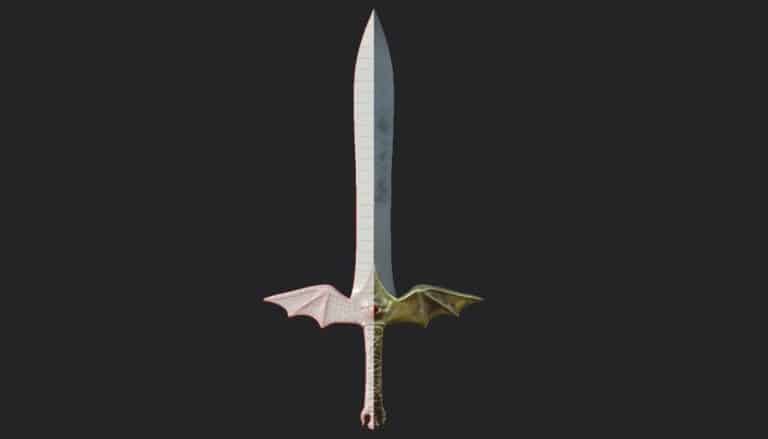
A Normal Map is a texture map that you can apply to your model to fake the detail of a high poly mesh. It does this by manipulating how light interacts with the model giving it the appearance it has more detail than it does.
This is extremely helpful to help reduce the resources needed to render a mesh, as potentially you can reduce a multi million poly model to just a few thousand polys.
As I have already mentioned a Normal Map is a RGB map and hence very difficult to create in something like photoshop. There is a specific set of steps required to produce one using 3d modelling software.
Below is an example of a Normal Map.
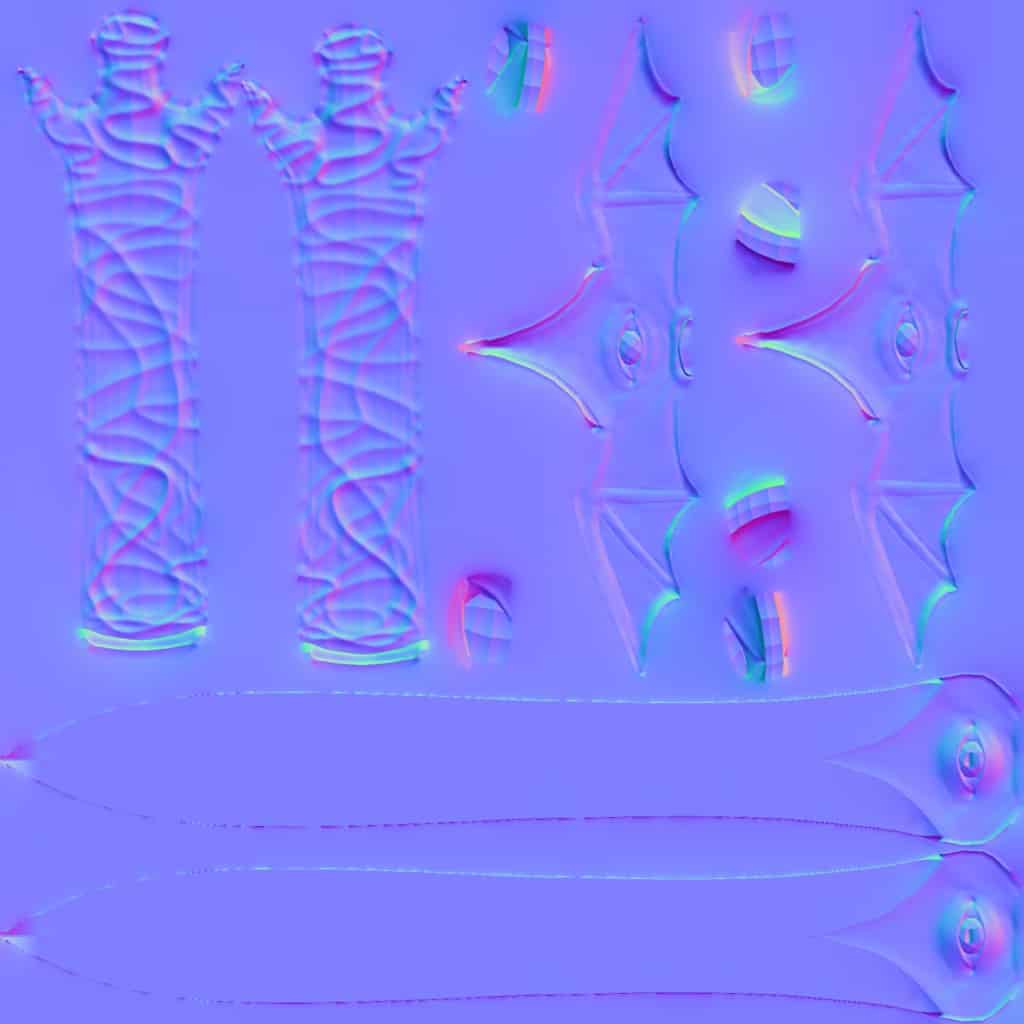
A Normal Map is just one of a few maps that do a similar manipulation of your model. There is also a Bump Map and a Displacement Map. For more info on these, what they are and how to use them I’d recommend you check out this post I wrote outlining all the most common texture maps you are likely to use.
Steps to Create One
To create a Normal Map there are 4 main steps they are as follows.
- Create the High Poly Model
- Retopologize to Low Poly Model
- Create a UV on the Low Poly Model
- Make the Normal Map
Step 1: Create the High Poly Model
The first step in creating a Normal Map is simply just having a model. At this stage you wont worry about poly count. Simply model, sculpt and use any tool at your disposal to create what you want the final version of your model to look like.
At this stage you do not need to worry about good topology, poly count, texturing or anything like that. This is usually the most fun part of the process as you can let your creativity take front seat with no limitations.
Step 2: Retopologize to Low Poly Model
Now that you have your model looking perfect there is a good chance it has a lot more polys than it needs. It is time to create the low poly version and this means you need to Retopologize. During this step you Do not overwrite the high poly version you need both.
This step is usually the most dreaded step of the process as it can be tedious and difficult. Retopology is the process of either reducing the poly count of a model, or modifying it so as to the topology is ideal for a modelling pipeline.
Many programs have both automatic and manual tools for doing this. The Manual tools usually require you to place each individual poly. The automatic tools use algorithms to place them for you.
While automatic options can save a lot of time, from my personal experience doing this manually gets the best results. Most automatic options are not sophisticated enough to properly layout topology.
When creating the low topology version you do not need to maintain the detail of the high poly version, you are simply looking to keep the general shape.
Take a basketball for example. There are fine divots and creases in its surface. In the low poly version you would not need to model these. It would be as simple as having a sphere the same size an shape as the ball. Once you create the normal map you will wrap the ball with the texture giving it detail.
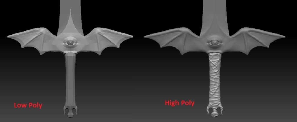
Below is an example of a high poly mesh vs the low poly version. Note the difference in detail particularly on the handle. A Normal Map is more than capable of creating this.
Step 3: Create a UV on the Low Poly Model
The next step is to create what is referred to as a UV of the low poly version of the model.
A UV is simply a 2d representation of a model laid out on a square grid.
Once again referring to the basketball example. If you made cuts in a basketball in a certain way you would be able to lay it out flat. In fact where the seams are on a basketball is perfect as splitting a basketball based on these seams would accomplish exactly that.
By creating a UV you are essentially allowing yourself to use any imaging software such as photoshop to directly draw on the model. In the case of a Normal Map applying the RGB colours to create the map.
To do this you have to place what are referred to as seams in your model so the modelling program knows where to cut. Once again there are both automatic and manual ways to do this. Once again I would personally choose a manual option as you have more control where to place these.
Seam placement can be important as if they are in noticeable areas it can cause inconsistencies in you textures.
Once you have you seams you can do what is referred to as unwrapping your mesh. This means you now take apart your mesh and arrange them on your square grid to best utilize its space
Below is an example of a UV created in Blender
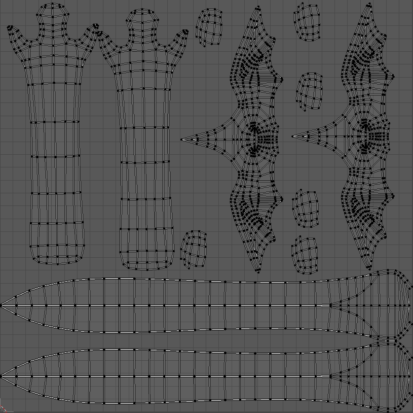
This can be done in standard pieces of software such as Blender or Maya.
Step 4: Make the Normal Map
The final step is easy as you now have everything you need to create the Normal Map. You should have the High Poly and Low Poly version of your model. Also the Low poly version should contain a UV Map.
If you have all three you’re good to go. Most modelling software will have a map baking function such as Blender. If it does not I would highly recommend XNormal. XNormal makes it incredibly easy to create Normal Maps with reasonably good results. Best of all it’s FREE!!
Regardless of the program you use simply follow the process and in no time you will have a Normal Map that you can apply to your model.
Common Mistakes
Not Enough Topology
During the retopology stage it is very easy to cut back on topology to much this often results in sharp edges appearing on the mesh.
When retopologizing ensure you maintain the general form of the model, any large variations in the model may need additional topology to support the Normal Map.
A Normal Map should supplement the small detail not the overall shape. So large craters or limbs need to be in the low poly mesh.
Smoothing Normals
This is not so much of a mistake but a bit of a trick. Before exporting your low poly mesh smooth your normals. Most 3d programs have this option.
What it does it smooths all the hard edges in the final render with no additional polys required. This helps compensate for the hard edges protruding out of your low poly mesh while the Normal Map is applied. This also allows you to limit your poly count further.
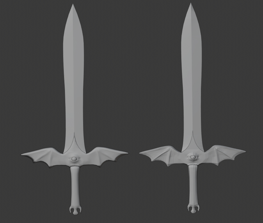
You can see the differences below. The model on the left has smoothed normals while the one on the right does not. Generally smoothing the normals gives better results.
Different Size Meshes
Often when you perform such actions like subdivision on the mesh it can actually shrink your High Poly Mesh in comparison the the Low Poly Mesh. This is not ideal as when it comes to baking it may not have the desired effect, or barely any effect at all.
If this is happening simply scale your high poly version bigger and try again. They don’t need to be the same size in fact it can sometimes be better if the High Poly Version is slightly bigger.
Conclusion
Now that you have an idea of what a Normal Map is, how it works and how to create one I highly encourage you to try these out. They are great if you are intending on using a model for games or animating as they can greatly conserve computer resources.
They are by far one of the most innovative tools in 3d modelling and used industry wide. If you haven’t given them a go then do they are not as scary as they look.
Good luck and keep experimenting.